The upper sheave (pulley) is the top of the drive system connecting the engine to the main drive shaft (which drives both the main rotor and the tail rotor). The upper sheave is jacked up and down by the clutch system. When it is in the lower position, the belts are slack and the engine can run without turning the rotor system. When the clutch system is engaged, the clutch motor jacks the upper sheave up until the belts are tight.
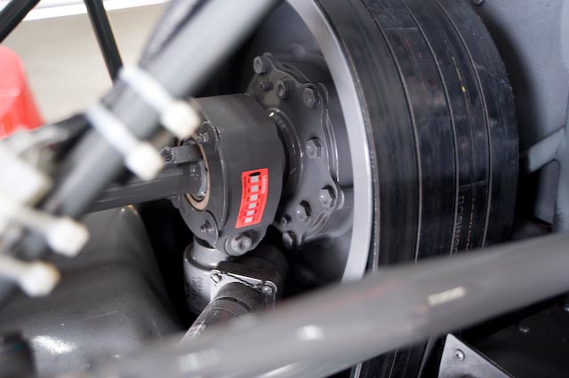
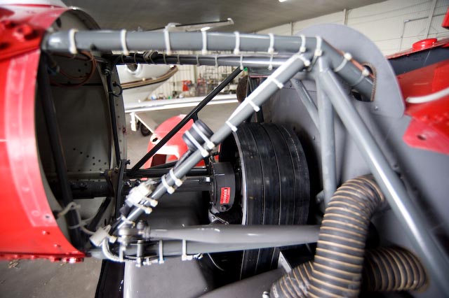
In this picture, you can see the four double belts on the upper sheave. Just to the left of the four belts, you can see the orange teletemp mounted on the upper bearing. The purpose of the upper bearing is to hold the drive shaft up (or down) while allowing it to turn. Because bearings can run hot before failure, the teletemp will give you an idea of the temperature the bearing has been running at. If the bearing suddenly starts to run hot, that would indicate a developing problem.
Just to the right of the upper bearing, built into the hub of the upper sheave is the freewheeling unit (sprag clutch). The purpose of the freewheeling unit is to allow the rotor to keep turning if the engine stops (so you can autorotate). Many people are confused when we talk about clutches in the Robinson, because there are two mechanisms located in approximately the same location. Jacking the upper sheave up and down tightens and loosens the belts - that is the drive engagement clutch (the one you activate in the cockpit by flipping the "clutch" switch). The freewheeling unit (sprag clutch) is built into the hub of the upper sheave and automatically allows the rotor to coast, in much the same way that a coaster brake in a bicycle allows you to pedal to turn the wheels, but allows you to stop pedalling while the bicycle continues to coast forwards.
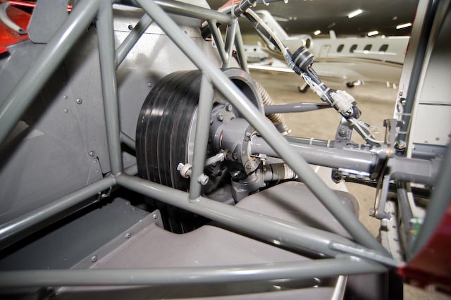
This is the same area, photographed from the other side. You can see the details of the rear frame in this picture.
Towards the right side of the picture you can see the rear flex coupling. The purpose of the flex couplings is to act as a universal joint, allowing the shaft to have some freedom to move up and down as the clutch is engaged and disengaged.

Here is even more detail of the flex coupling. The thin central plate is the flex plate. It is designed to be flexible enough to allow some bending of the shaft. The two thick pieces of metal that it connects (one on the main transmission side, one on the tail rotor transmission side) are called the yoke flanges.
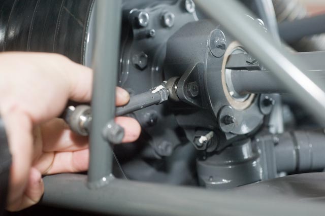
Notice the rod connecting the upper bearing to the frame (that I'm touching in the picture). This rod keeps the drive shaft centered laterally. The jack shaft positions the drive shaft vertically, but something needs to keep the shaft aligned with the transmission, yet allow the shaft to move up and down. Because it is a simple rod, the shaft must move laterally a little when the bearing is jacked up and down. Presumably it is designed so that it is perfectly centered when the drive system is in the engaged position, and that both the main rotor and tail rotor transmissions are built to allow a little lateral motion of the shaft.

In this picture you can see the clutch motor. The clutch motor runs to jack the upper bearing up or down, depending on the position of the clutch switch. Many people have the misconception that the clutch will adjust the tension of the belts in both the tighten and slacken directions in flight. In fact, when you switch the clutch switch in the cockpit one of the things you are setting is the direction the motor will run. If the switch is in the engage position, and you see the clutch light come on, the motor is running to tighten the belts.
In the POH you are cautioned to pull the clutch breaker if it runs for more than 7-8 seconds in flight. That is because the motor is strong enough to break the belts (and in flight the belts should already be tensioned and not need anywhere near 7 seconds of additional tightening - in fact if that happens what has probably occurred is that you have already broken one of the belts, and the clutch mechanism is trying to restore proper tension by increasing tension on the remaining belts).
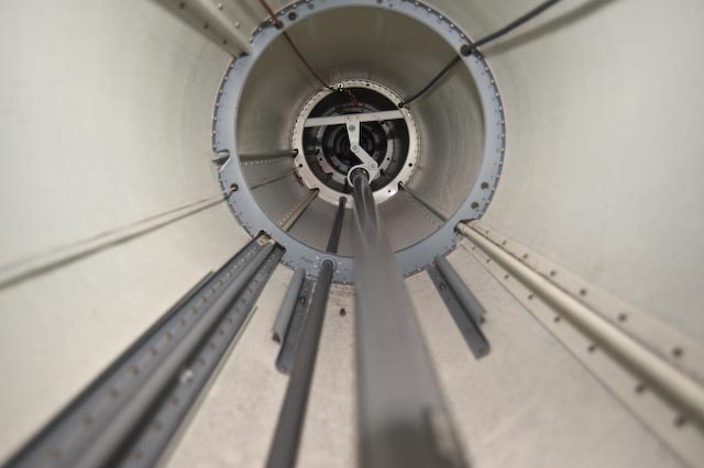
In this picture we are looking from the upper sheave area back towards the tail rotor down the inside of the tailcone. You can see several interesting features in this picture. There are wires for the strobe light, the position light, and the chip detector. The tail rotor control push pull tube is running just to left of center at the bottom of the photograph. The long tube in the center is the tail rotor drive shaft. You can see the hanger bearing halfway down the tail boom.

Finally, this picture shows an overall view of the upper sheave area from above. You can see the upper sheave to the right, the bearing just to the left of the sheave, the clutch motor on a 45 degree angle just below the upper bearing, and the driveshaft going back through the flex coupling and continuing on into the tailcone.
Just below the drive shaft, the horizontal tube that connects to the bellcrank (just above the wireing bundle) is the tail rotor pitch control tube. In the left part of the photograph, the two bolts, one at the top and one at the bottom with light blue torque paint on them are the bottom two tailcone attach bolts. The grey area in the center of the picture, below the drive shaft is the top of the fan shroud.