
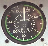
The airspeed indicator is calibrated in both knots and miles per hour. The green arc shows the normally allowed operating range. The red line marks the maximum VNE (never exceed speed) of 130 knots. The VNE changes depending on weight of the aircraft and density altitude. At aircraft weights of 3,000 lbs and below, the VNE decreases by 3.5 knots per 1,000 feet above 3,000 feet density altitude. When the aircraft weight is above 3,000 pounds, the VNE goes down by 122 knots maximum, and decreases by 7 knots per 1,000 feet above 3,000 feet density altitude.
Other VNE limits are 80 knots above 85% torque (it bends the mast too much!), 87 knots with aft doors off, and 69 knots with forward doors off.
The blue line is a reminder to the pilot of maximum airspeed during
autorotation of 100 knots.
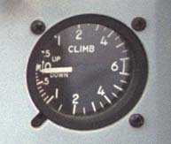
The VSI is mounted directly below the altimeter in the JetRanger.
The vertical speed indicator is like an altimeter, but shows how
rapidly altitude is changing. Between -1,000 feet per minute and
+1,000 per minute, each mark indicates 100 feet per minute of vertical
speed. Beyond 1,000 feet per minute each mark is 500 feet per minute. This
particular gauge can show a maximum climb or descent rate of 6,000 feet
per minute (which is 68 mph straight up or down!)
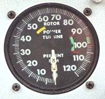
The dual tachometer in the Bell JetRanger is mounted to the left of the directional gyro. Two concentric indicators display the main rotor RPM (Nr) and the power turbine RPM (N2):
The labeling on the gauge is confusing, since the words "ROTOR" and "POWER TURBINE" would lead you to believe that the rotor is the outer ring and the power turbine is the inner ring. In fact, it is just the opposite.
The green arcs depict the operating limits for the rotor and power turbine. The power turbine (N2) must be operated between 97% to 100%. The rotor (Nr) may be operated between 90% and 100%.
The yellow arc indicates a range the pilot should avoid, i.e. he should
accelerate rapidly through this RPM range.
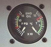
This is a dual instrument, displaying engine oil pressure on the left side, and engine oil temperature on the right. It is mounted in the upper left corner.
Engine oil pressure limits are based on Gas Producer (N1) RPM. Below 78.5% N1, minimum pressure is 50 PSI. Between 78.5 and 94.2% N1, minimum is 90 PSI. Above 94.2% N1, minimum pressure is 90 PSI and maximum pressure is 130 PSI.
Engine oil temperature limits are 0 degrees centigrade to 107 degrees
centigrade.
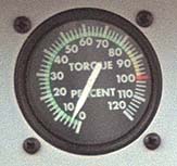
This gauge is mounted just to the right of the Engine Oil gauge and indicates the torque output of the engine.
The continuous operating range for torque is 0-85%. The pilot may use
between 85-100% torque for up to 5 minutes. A 5 second transient limit
is set at 110%, but the pilot may not intentially use this amount of power.
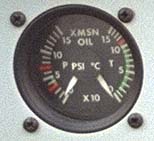
This is a dual instrument, displaying main rotor transmission oil pressure on the left side, and main rotor transmission oil temperature on the right.
Oil pressure operating range is 30 to 50 psi. A maximum of 70 PSI is allowable during warmup.
Oil temperature operating range is between 15 to 100 degrees Centigrade.
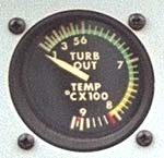
This gauge is mounted just below the torque gauge, and indicates the turbine outlet temperature.
The maximum TOT for continuous operation is 738 degrees centigrade. A maximum
TOT of 810 degrees centigrade may be used for up to 5 minutes. A transient
limit of 843 degrees centigrade for 6 seconds is allowed, but the pilot may
not use it intentionally. During startup and shutdown the TOT limits are
between 810 and 927 degrees centigrade for a maximum of 10 seconds.
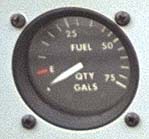
This gauge displays gallons of fuel remaining in the fuel cell. JetRangers
with serial numbers above 3567 have a gauge which goes up to 100 gallons.
This one only goes up to 75, even though the fuel extender allows us to fit
almost 100 gallons in the fuel cell.

This gauge displays turbine RPM (N1). Because the engine is a "free" turbine, the compressor and gas generator turbine can turn at one RPM while the "power" turbine turns at another RPM. The large pointer is calibrated in 2% increments. The little dial in the lower right of the instrument is calibrated in 1% increments. Each complete rotation of the little indicator represents 10%.
The N1 operating limitations are 105% maximum, transient limit of 106% for
15 seconds.
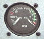
This gauge is a dual instrument, displaying generator load on the left side, and fuel pump pressure on the right. Fuel pressure limitations are minimum 4.0 PSI, maximum 30.0 PSI. There are two electric boost pumps as well as the engine driven fuel pump. The engine driven fuel pump can supply sufficient fuel pressure to run the engine up to 6,000 feet. Either boost pump can provide enough additional pressure to run the engine up to maximum altitude, however both pumps must be operated in flight. If one boost pump fails, the pilot descends below 6,000 feet if possible, so that if the remaining boost pump fails the engine does not flame out. Failure of the engine driven fuel pump will always flame out the engine.
The loadmeter shows output of the generator as a percentage of maximum. The
maximum allowable load is 70%.