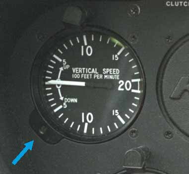
In this close up picture, the blue arrow points at the zero adjustment screw. Each mark above the zero represents a climb rate of 100 feet per minute. Each mark below the zero represents a descent rate of 100 feet per minute.
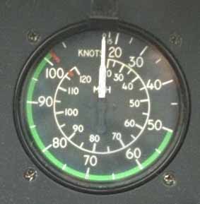
The next spot over is the Airspeed Indicator. The outer scale is in knots
(nautical miles per hour), the inner scale is marked in mph (miles per
hour). The red line is marked at the VNE or "Never Exceed Speed" of 102
knots.
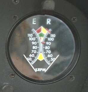
The right hand instrument in the upper row is the dual tachometer:
The left hand needle indicates Engine RPM (revolutions per minute), the
right hand needle indicates Main Rotor RPM. The colored arcs indicate
normal, caution, and prohibited ranges. For instance, on the Engine side
(left) there is a green arc from 97% to 104%. Above and below this are
red, as the engine should not be operated outside this range during
flight. However, if you look at the Rotor side (right) you will notice
that green again goes from 97% to 104%, but below and above that there is
a yellow area. This means the rotor system can be operated between 90% and
97%, and also from 104% to 110% while in flight. This allows the pilot a
larger range of allowable RPM while autorotating. The yellow range between
60% and 70% is an area where the tail boom and main rotor resonate. It is
marked yellow to warn pilots to avoid extended operation in this range
during startup and shutdown.
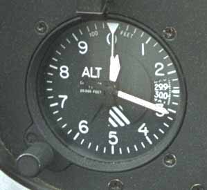
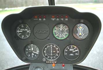
On the right row, the left most instrument is the Altimeter:
This instrument senses barometric pressure and indicates height above sea
level based on that pressure. Most altimeters (including this one) are
sensitive altimeters in that the pilot can turn an adjusting knob
to compensate for non-standard pressure. The altimeter looks a lot like a
clock, with a long arrow shaped indicator and a short arrow shaped indicator.
The short indicator indicates thousands of feet. Here it is about 1/3 of the
way from 0 to 1 because we are about 300 feet above sea level. The long
indicator indicates in hundreds of feet. It is pointing at the 3, so we are
at about 300 feet. Each mark between numbers is 20 feet, so we are indicating
about 310 feet here. The long thin white indicator which goes up through the
zero is the 10,000 foot marker. I've never seen that move much in a helicopter!
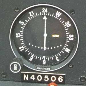
The gauge second from the left on the bottom row is an optional gauge.
In this case the helicopter has a VOR navigation radio installed. This is
fairly rare in VFR helicopters because they tend to fly too low to pick up
many VOR signals.
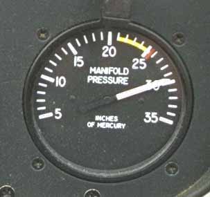
The rightmost bottom gauge is the Manifold Pressure gauge:
The pilot uses this gauge to determine the throttle setting. In the R22
the pilot calculates a maximum manifold pressure given the current
temperature and pressure. By calculating this maximum and not exceeding
it, the pilot derates the engine from the 160 horsepower which is actually
available, to the derated maximum which is 124 horsepower continuous, or
131 horsepower for up to 5 minutes. Derating the engine prolongs the
useful life of the engine, making it more reliable than if full power was
being used on a regular basis. It also means that full power is available
to a higher altitude just as if the engine was turbocharged.
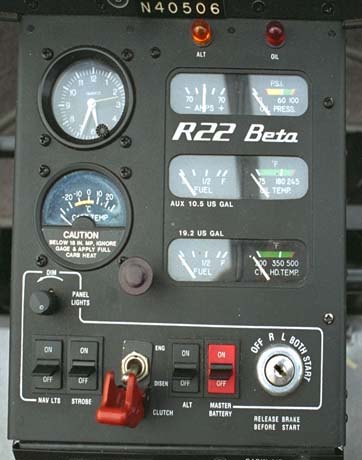
Just below the carburetor air temperature gauge is a potentiometer which allows the pilot to adjust the brightness of the panel lights during night flight. Along the bottom, from left to right we have "Nav Lights" which turns on the red, green, and white position lights. Second from the left is the strobe light which activates a flashing light on the tail and optionally under the belly, then the clutch switch which activates the R22 electric rotor engagement clutch system. Next to that is the alternator switch, the battery switch, and the magnetos/starter key switch.
In the upper left is an electronic outside air temperature gauge. This is something I wish other manufacturers would do. It's much easier to read than the normal thermometer stuck through the overhead window trick. This one reads in either Farenheight or Celcius.
To the right of the OAT gauge, is the landing light switch, and a warning light that indicates that the rotor brake is engaged (so you won't try to start the helicopter with the brake activated). The big knob on the right opens the forward fresh air vent.
The radio stack in this case consists of a Loran navigational radio on top, a combination communications and navigation radio in the middle (which drives that VOR indicator on the upper panel) and a Mode C transponder on the bottom which makes the aircraft more visible on radar displays.
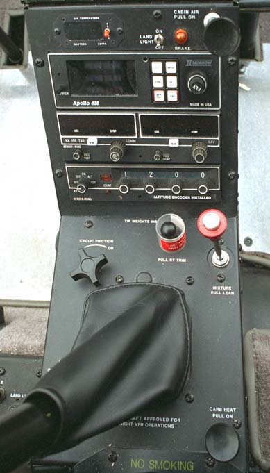
On the bottom panel upper left is the friction for the cyclic control. This can be used on the ground and in flight. To the right of that is the right trim knob which has the mixture guard sitting on it right now. The right trim device reduces the tendency of the cyclic to pull to the left in high speed flight. In flight the mixture guard is placed on the mixture control to prevent it being pulled in flight accidentally. On the far right is the mixture knob. Here at sea level this is mostly used either full in when the engine is running, or full out to stop the engine. At high altitude you would pull the control part way out to prevent an over rich fuel mixture.
In the lower right corner of the photo you can see the carburetor heat control. This introduces heated air into the carburetor to melt any ice which has formed. Unlike most airplanes, this air is filtered and thus can be used on the ground.