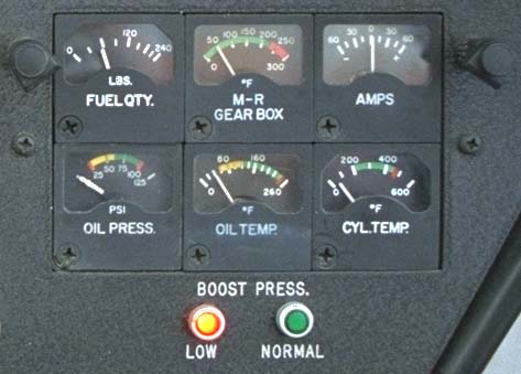
In the upper left corner we currently have a clock mounted. Previously this panel position held an EGT. Below and to the left of the clock you can see a red light. This is a warning light that the clutch is not engaged. The clutch on the Enstrom is mechanical and takes quite a strong pull to engage.
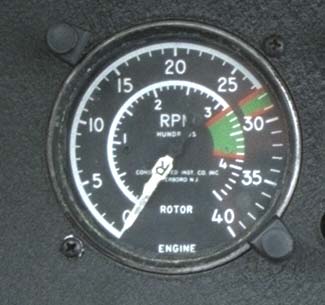
The dual tachometer in the Enstrom is a mechanical instrument, connected to the main rotor and engine by cables.
The outer scale displays to engine RPM (revolutions per minute), while the
inner scale displays rotor RPM. The red lines show the legal range: the
engine must be operated between 2750 and 2900 RPM while in flight. The
main rotor must be operated between 313 and 385 RPM while in flight. The
higher upper rotor limit allows the pilot to build RPM during the
autorotation flare, giving him a massive amount of energy available for
touchdown without an engine.

This instrument senses barometric pressure and indicates height above sea level based on that pressure. Most altimeters (including this one) are sensitive altimeters in that the pilot can turn an adjusting knob to compensate for non-standard pressure. The little window on the right side of the instrument (partially obscured by the large indicator hand) tells the pilot what pressure the altimeter is set for. In this case, it's set for about 29.94 inches of mercury.
The altimeter looks a lot like a clock, with a long arrow shaped indicator
and a short arrow shaped indicator. The short indicator indicates
thousands of feet. Here it is about 1/4 of the way from 0 to 1 because we
are about 250 feet above sea level. The long indicator indicates in
hundreds of feet. It is pointing halfway between the 2 and the 3, so we
are at about 250 feet. Each mark between numbers is 20 feet, so we are
indicating about 260 feet here. If you compare this altimeter with the
ones in our Robinsons and JetRanger, you'll notice that this one does not
have a 10,000 foot pointer. Enstrom is being realistic about how high this
helicopter can go!

This instrument displays airspeed as measured by the pitot tube. The pitot tube is just a piece of tubing on the front of the helicopter pointing directly forward. As the helicopter moves forward, air is rammed into the tube. The air being rammed in increases the pressure inside the instrument and the pressure moves the indicator:
This indicator is calibrated in MPH (miles per hour). The VNE (never exceed
speed) is indicated by the red line at 112 miles per hour. However, there is
a chart the pilot uses to calculate VNE given temperature and pressure and
on a typical summer day the VNE will be lower than 112.

The vertical speed indicator is like an altimeter, but shows how rapidly altitude is changing. Each mark above the "0" indicates 100 feet per minute of climb rate. Each mark below "0" indicates 100 feet per minute of descent rate. This particular gauge can show a maximum climb or descent rate of 3,500 feet per minute.
You may notice that this gauge is marked "IVSI" which stands for "Instantaneous Vertical Speed Indicator". When we first got this aircraft, it had no VSI at all. Students requested that it be fitted with one. At first, a normal airplane VSI was fitted (by mistake). The problem is that normal VSIs have a great deal of lag, i.e. it takes several seconds for them to adjust to changes in climb or descent rate. This causes a problem for a helicopter because the descent rate is constantly changing on approach, and if the lag is too long (which it was in the particular instrument we had) the gauge is essentially useless because it is displaying information that is out of date.
An instantaneous VSI has extra mechanical linkages to sense a change in the
rate of altitude change, and it moves the indicator in response to that
change. The result is a faster indication that the pilot has changed his
rate of climb or descent.
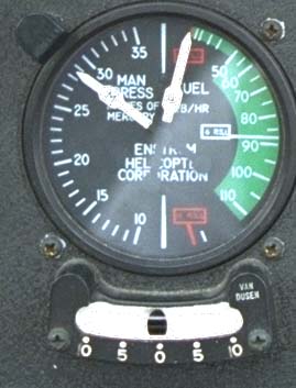
This is a dual instrument, displaying manifold pressure on the left side and fuel flow on the right side. Below the gauge is the inclinometer, which is used to determine whether the aircraft is in trim. In this case, the position of the ball directly above "0" means we are in trim.
The manifold pressure gauge indicates the atmospheric pressure inside the intake manifold. The engine is not running in this photograph, therefore the guage is indicating ambient pressure, slightly below 29.00 inches of mercury. Normally we use about 15 inches of manifold pressure to descend, 23 inches of manifold pressure to cruise, and 25-27 inches of manifold pressure to hover and takeoff.
The fuel flow gauge shows the fuel flow rate going into the engine. This
will depend on the throttle setting. Typically at cruise power settings,
we burn about 90 pounds per hour. During hover and climb we burn about 105
pounds per hour. Because the fuel quantity gauge is calibrated in pounds,
it's very simple for the pilot to use the fuel flow gauge and fuel
quantity gauge to estimate how long he can fly at the current power
setting.